Sample OSI Model Assignment Help | Sample OSI model assignment answer
OSI MODEL DESCRIPTION for sample OSI model assignment answer
The Open System Interconnection Reference Model (OSI Reference Model or OSI Model) is an abstract description for layered communications and computer network protocol design. It was developed as part of the Open Systems Interconnection (OSI) initiative. In its most basic form, it divides network architecture into seven layers which, from top to bottom, are the Application, Presentation, Session, Transport, Network, Data-Link, and Physical Layers. It is therefore often referred to as the OSI Seven Layer Model. The model was developed by the International Organization for Standardization (ISO) in 1984, and it is now considered the primary architectural model for intercomputer communications. The OSI model divides the tasks involved with moving information between networked computers into seven smaller, more manageable task groups. A task or group of tasks is then assigned to each of the seven OSI layers.
A layer is a collection of conceptually similar functions that provide services to the layer above it and receives service from the layer below it. On each layer an instance provides services to the instances at the layer above and requests service from the layer below. For example, a layer that provides error-free communications across a network provides the path needed by applications above it, while it calls the next lower layer to send and receive packets that make up the contents of the path. Conceptually two instances at one layer are connected by a horizontal protocol connection on that layer
LAYERS OF OSI MODEL:

Layer | Function | Protocols | Network Components |
Application User Interface |
| DNS; FTP; TFTP; BOOTP; SNMP;RLOGIN; SMTP; MIME; NFS; FINGER; TELNET; NCP; APPC; AFP; SMB | Gateway |
Presentation Translation |
| Gateway Redirector | |
|
Session "syncs and sessions" |
|
NetBIOS Names Pipes Mail Slots RPC |
Gateway |
|
Transport packets; flow control & error-handling |
|
TCP, ARP, RARP; SPX NWLink NetBIOS / NetBEUI ATP | |
|
Network addressing; routing |
|
IP; ARP; RARP, ICMP; RIP; OSFP; IGMP; IPX NWLink NetBEUI OSI DDP DECnet | |
|
Data Link data frames to bits |
|
Logical Link Control
802.1 OSI Model 802.2 Logical Link Control |
Bridge Switch ISDN Router Intelligent Hub NIC Advanced Cable Tester |
|
Media Access Control
802.3 CSMA/CD (Ethernet) 802.4 Token Bus (ARCnet) 802.5 Token Ring 802.12 Demand Priority | |||
|
Physical hardware; raw bit stream |
|
IEEE 802 IEEE 802.2 ISO 2110 ISDN |
Repeater Multiplexer Hubs
TDR Oscilloscope Amplifier |
MAJOR FUNCTIONS OF LAYERS OF OSI MODEL IN ASCENDING ORDER
Layer 1: Physical Layer for sample OSI model assignment answer
The Physical Layer defines the electrical and physical specifications for devices. In particular, it defines the relationship between a device and a physical medium. This includes the layout of pins, voltages, cable specifications, hubs, repeaters, network adapters, host bus adapters (HBAs used in storage area networks) and more.
To understand the function of the Physical Layer in contrast to the functions of the Data Link Layer, think of the Physical Layer as concerned primarily with the interaction of a single device with a medium, where the Data Link Layer is concerned more with the interactions of multiple devices (i.e., at least two) with a shared medium. The Physical Layer will tell one device how to transmit to the medium, and another device how to receive from it (in most cases it does not tell the device how to connect to the medium). Standards such as RS-232 do use physical wires to control access to the medium.
The major functions and services performed by the Physical Layer are:
- Establishment and termination of a connection to a communications medium.
- Participation in the process whereby the communication resources are effectively shared among multiple users. For example, contention resolution and flow control.
- Modulation, or conversion between the representation of digital data in user equipment and the corresponding signals transmitted over a communications channel. These are signals operating over the physical cabling (such as copper and optical fiber) or over a radio link.
Parallel SCSI buses operate in this layer, although it must be remembered that the logical SCSI protocol is a Transport Layer protocol that runs over this bus. Various Physical Layer Ethernet standards are also in this layer; Ethernet incorporates both this layer and the Data Link Layer. The same applies to other local-area networks, such as token ring, FDDI, ITU-T G.hn and IEEE 802.11, as well as personal area networks such as Bluetooth and IEEE 802.15.4.
Layer 2: Data Link Layer
The Data Link Layer provides the functional and procedural means to transfer data between network entities and to detect and possibly correct errors that may occur in the Physical Layer. Originally, this layer was intended for point-to-point and point-to-multipoint media, characteristic of wide area media in the telephone system. Local area network architecture, which included broadcast-capable multiaccess media, was developed independently of the ISO work, in IEEE Project 802. IEEE work assumed sublayering and management functions not required for WAN use. In modern practice, only error detection, not flow control using sliding window, is present in modern data link protocols such as Point-to-Point Protocol (PPP), and, on local area networks, the IEEE 802.2 LLC layer is not used for most protocols on Ethernet, and, on other local area networks, its flow control and acknowledgment mechanisms are rarely used. Sliding window flow control and acknowledgment is used at the Transport Layer by protocols such as TCP, but is still used in niches where X.25 offers performance advantages.
The ITU-T G.hn standard, which provides high-speed local area networking over existing wires (power lines, phone lines and coaxial cables), includes a complete Data Link Layer which provides both error correction and flow control by means of a selective repeat Sliding Window Protocol.
Both WAN and LAN services arrange bits, from the Physical Layer, into logical sequences called frames. Not all Physical Layer bits necessarily go into frames, as some of these bits are purely intended for Physical Layer functions. For example, every fifth bit of the FDDI bit stream is not used by the Layer.
Layer 3: Network Layer
The Network Layer provides the functional and procedural means of transferring variable length data sequences from a source to a destination via one or more networks, while maintaining the quality of service requested by the Transport Layer. The Network Layer performs network routing functions, and might also perform fragmentation and reassembly, and report delivery errors. Routers operate at this layer—sending data throughout the extended network and making the Internet possible. This is a logical addressing scheme – values are chosen by the network engineer. The addressing scheme is hierarchical.
The best-known example of a Layer 3 protocol is the Internet Protocol (IP). It manages the connectionless transfer of data one hop at a time, from end system to ingress router, router to router, and from egress router to destination end system. It is not responsible for reliable delivery to a next hop, but only for the detection of errored packets so they may be discarded. When the medium of the next hop cannot accept a packet in its current length, IP is responsible for fragmenting the packet into sufficiently small packets that the medium can accept.
A number of layer management protocols, a function defined in the Management Annex, ISO 7498/4, belong to the Network Layer. These include routing protocols, multicast group management, Network Layer information and error, and Network Layer address assignment. It is the function of the payload that makes these belong to the Network Layer, not the protocol that carries them.
Layer 4: Transport Layer
The Transport Layer provides transparent transfer of data between end users, providing reliable data transfer services to the upper layers. The Transport Layer controls the reliability of a given link through flow control, segmentation/desegmentation, and error control. Some protocols are state and connection oriented. This means that the Transport Layer can keep track of the segments and retransmit those that fail.
Although not developed under the OSI Reference Model and not strictly conforming to the OSI definition of the Transport Layer, typical examples of Layer 4 are the Transmission Control Protocol (TCP) and User Datagram Protocol (UDP).
Of the actual OSI protocols, there are five classes of connection-mode transport protocols ranging from class 0 (which is also known as TP0 and provides the least error recovery) to class 4 (TP4, designed for less reliable networks, similar to the Internet). Class 0 contains no error recovery, and was designed for use on network layers that provide error-free connections. Class 4 is closest to TCP, although TCP contains functions, such as the graceful close, which OSI assigns to the Session Layer. Also, all OSI TP connection-mode protocol classes provide expedited data and preservation of record boundaries, both of which TCP is incapable. Detailed characteristics of TP0-4 classes are shown in the following table:
Perhaps an easy way to visualize the Transport Layer is to compare it with a Post Office, which deals with the dispatch and classification of mail and parcels sent. Do remember, however, that a post office manages the outer envelope of mail. Higher layers may have the equivalent of double envelopes, such as cryptographic presentation services that can be read by the addressee only. Roughly speaking, tunneling protocols operate at the Transport Layer, such as carrying non-IP protocols such as IBM's SNA or Novell's IPX over an IP network, or end-to-end encryption with IPsec. While Generic Routing Encapsulation (GRE) might seem to be a Network Layer protocol, if the encapsulation of the payload takes place only at endpoint, GRE becomes closer to a transport protocol that uses IP headers but contains complete frames or packets to deliver to an endpoint. L2TP carries PPP frames inside transport packet.
Layer 5: Session Layer
The Session Layer controls the dialogues (connections) between computers. It establishes, manages and terminates the connections between the local and remote application. It provides for full-duplex, half-duplex, or simplex operation, and establishes checkpointing, adjournment, termination, and restart procedures. The OSI model made this layer responsible for graceful close of sessions, which is a property of the Transmission Control Protocol, and also for session checkpointing and recovery, which is not usually used in the Internet Protocol Suite. The Session Layer is commonly implemented explicitly in application environments that use remote procedure calls.
Layer 6: Presentation Layer
The Presentation Layer establishes a context between Application Layer entities, in which the higher-layer entities can use different syntax and semantics, as long as the presentation service understands both and the mapping between them. The presentation service data units are then encapsulated into Session Protocol data units, and moved down the stack.
This layer provides independence from differences in data representation (e.g., encryption) by translating from application to network format, and vice versa. The presentation layer works to transform data into the form that the application layer can accept. This layer formats and encrypts data to be sent across a network, providing freedom from compatibility problems. It is sometimes called the syntax layer.
The original presentation structure used the basic encoding rules of Abstract Syntax Notation One (ASN.1), with capabilities such as converting an EBCDIC-coded text file to an ASCII-coded file, or serialization of objects and other data structures from and to XML.
Layer 7: Application Layer for sample OSI assignment help
The application layer is the OSI layer closest to the end user, which means that both the OSI application layer and the user interact directly with the software application. This layer interacts with software applications that implement a communicating component. Such application programs fall outside the scope of the OSI model. Application layer functions typically include identifying communication partners, determining resource availability, and synchronizing communication. When identifying communication partners, the application layer determines the identity and availability of communication partners for an application with data to transmit. When determining resource availability, the application layer must decide whether sufficient network resources for the requested communication exist. In synchronizing communication, all communication between applications requires cooperation that is managed by the application layer. Some examples of application layer implementations include Hypertext Transfer Protocol (HTTP), File Transfer Protocol (FTP), Simple Mail Transfer Protocol (SMTP) and X.400 Electronic Mail.
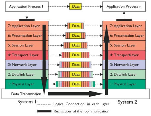
DIAGRAMMATIC REPRESENTATION OF THE MOVEMENT OF DATA THROUGH ALL SEVEN LAYERS